Editing fault cutoff lines
After the fault cutoff lines have been calculated using the Fault Cutoff Line Edits form, you can manually adjust the lines so that they better fit your interpretation of the structure. The initial positions of the fault cutoff lines are derived from the surface geometry in the context of the model hierarchy and the layer alignments. The position of the fault cutoff lines will remain subject to the surface geometry, model hierarchy and layer alignments until a manual edit to the fault cutoff line is made. Once an edit is made on a fault cutoff line, its position is fixed to honor your decision; the next time surfaces are constructed, your edits will take precedence over the surface geometry, model hierarchy and layer alignments. Using this process, you can exert your influence over the model to produce the desired result.
How fault cutoff line edits are handled
Control nodes and lines
Direct interaction with fault cutoff lines is performed by interacting with control nodes, either through manual interaction with the editing tools, or via the context menu. Initially, control nodes are copies from the nodes of the existing fault cutoff line, and become visible as orange nodes when you select an editing tool (on the Workspace > Tools > Editing Tools) for the respective fault cutoff line. These control nodes can subsequently be moved, however, only within the fault plane. The control nodes are connected with a line, the so-called 'control line'. A control line is related to a fault block, and starts and ends where the fault block starts and ends. This means that when a fault is intersected by other faults, its fault cutoff line can have multiple control lines (each faultblock has its own control lines, see image below).
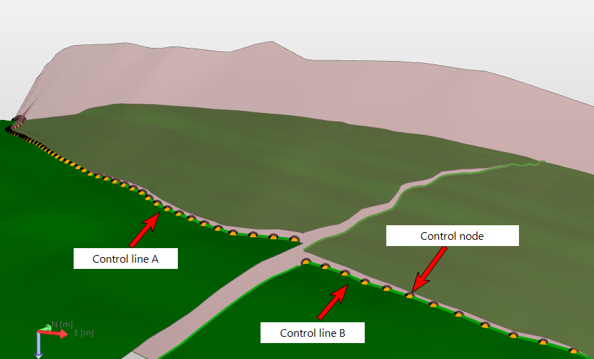
Image showing the hanging wall fault cutoff line of a NW-SE oriented fault having two control lines due to a NE-SW oriented intersecting fault. Note that editing one or more control nodes of control line A will set the entire control line A as edited/locked. Control line B, on the other hand, will keep the status 'unedited/unlocked'. click to enlarge
A control line and its control nodes form one entity, which means that when one control node is edited, all other nodes of the same control line will be considered 'edited', even if you did not move them. In other words, the position of all control nodes of that control line will be 'fixed' in space ('locking' a node with the 'lock' option only applies to that particular node, see further below). Active (orange) control nodes of one fault cutoff line can be visible at any time. When you make your edits to the control nodes, no change is made to the actual fault cutoff line until the Apply button is clicked on the Fault Cutoff Line Edits form.
When you adjust control nodes, a preview of the fault cutoff line is visualized in the view as a thin line. This preview represents an estimation of how the fault cutoff line will be rendered when the edits are applied and the surfaces are constructed. See the image below, where four control nodes have been moved upwards. The thin green line and black nodes are the preview of the estimation of the fault cutoff line (the preview line adopts the surface color).
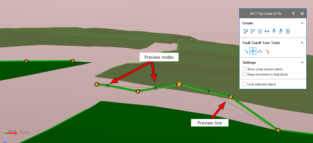
An example of control node editing. Four orange control nodes have been moved upwards. The thin green line and black nodes show the estimation of the fault cutoff line (the preview takes the color of the surface). Note that in this example, the new node positions are deliberately 'scattered' in order to make the (thin green) preview of the estimated fault cutoff line visible. click to enlarge
When a control end-node (i.e. the control node at the end of a control line) is moved but remains too close to its neighbor, the new position cannot be honored and the control end-node will be ignored, see image below.
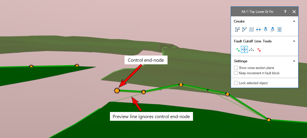
The control end-node has been moved, but is positioned too close to the neighboring control node. For that reason it cannot be honored, as shown by the preview of the fault cutoff line (i.e. the thin green line) and which connects to the original end-node position. click to enlarge
Editing control nodes
You can reposition, add and remove control nodes in order to influence the path of the fault cutoff line. Changes to the control nodes are performed using the Editing Tools in the Solve Fault Cutoff Lines 3D View. With the Editing Tools open and the fault cutoff line of interest visible in the view, you can use the following three Editing Tools buttons to make your changes:
 Add Node (Shortcut key: Q) The application automatically generates control nodes for editing based on the modeling parameters of the 3D structural model and the resampling of the fault cutoff lines. Nodes can be added to the control lines to aid in making fine adjustments to the control line. To add a node, click the Add node button on the Editing Tools palette and then click on the control line at the position you want to add the node.
 Move Node (Shortcut key: M) Control nodes can be moved both vertically and laterally (with some constraints) using the Move node button on the floating palette. To move a node, click the Move node button, click a control node to make it active, then press and hold Ctrl on your keyboard while clicking and dragging the node to the new position. When moving a node laterally, the range of movement is restricted in order to prevent a self-intersecting line.
 Move Nodes Along Curve (Shortcut key: Ctrl+M) A series of adjacent nodes can be moved along the fault plane using the Move Nodes Along Curve button on the floating palette. Click on the button on the palette, then press Shift and select at least three nodes in the view. Then drag one of the nodes (it does not matter which node, but preferably not one of the end-nodes); all selected nodes (apart from the end-nodes) will be moved according to spline interpolation.
 Remove Node (Shortcut key: Ctrl+Q) You can remove nodes using the Remove node button on the floating palette. To remove a node, click the Remove node button, then click the node you wish to remove. When removing nodes, the control line will adjust automatically to account for the removal of the node. This is an important consideration, as the application will then draw a straight line between the two nodes that are positioned on either side of the removed node. In other words, if the removed node was causing the fault cutoff line to angle between its neighbor nodes, that angle is lost when the anchoring node is removed.
Editing multiple nodes
You can move and remove multiple nodes in one action using the Shift and Ctrl keys:
Moving multiple nodes First, activate the fault cutoff line of interest and select the Move Node option from the Editing Tools palette. Hold Shift and Ctrl while clicking and dragging a selection box around the control nodes that you want to move. All of the control nodes that fall inside the selection box are selected. After multiselecting, the Shift and Ctrl keys can be released. To move the group of control nodes, hold down the Ctrl key, click one of the selected nodes and drag to the desired position. You can also move multiple nodes along a curve (the curve is based on spline interpolation), see Move Nodes Along Curve above.
Removing multiple nodes First, activate the fault cutoff line of interest and select the Remove Node option from the Editing Tools palette. Hold Shift and Ctrl while clicking and dragging a selection box around the control nodes you want to remove. When you release the mouse button to finalize your selection, the nodes are immediately removed.
Reviewing edits (highlight edits)
By default, pending edits are visualized in the Solve Fault Cutoff Lines 3D View. You can toggle the display of edits using the Highlight Edits context menu option. To do so, right-click the fault cutoff line of interest and select the Highlight Edits option. The nodes that have been altered are displayed at their original location in the view and take the same color as the fault cutoff line, as opposed to the control nodes, which are orange in color.
Undo and redo action
You can undo and redo up to five editing actions using the Undo ![]() and Redo
and Redo ![]() buttons at the top of the strip.
buttons at the top of the strip.
Locking lines, segments and nodes
In addition to constraining fault cutoff line position via manual edits, you can choose to fix the position of a fault cutoff line, a control line (i.e. segment) or an individual node by 'locking' it. This can be done using the Fault Cutoff Lines form or the context menu of the item in the Solve Fault Cutoff Lines 3D View. The locked (or edited) status will fix the fault cutoff line, control line or node in space using it as a constraint in the construction of the 3D structural model. This means it will affect the geometry of its corresponding horizon (within the clean-up distance) and that of potential dependent horizons and their fault cutoff lines.
Locking items in the Fault Cutoff Line Edits form You can lock an entire fault cutoff line by right-clicking it in the table of the Fault Cutoff Lines form and selecting Lock from the context-menu.
Locking entire fault cutoff lines, control lines and control nodes using the context menu Right-click the fault cutoff line, control line (called 'segment' in the context menu) or node, hover over the Lock option in the context menu and select the item you wish to lock.
Removing edits/lock In order to delete all edits of a fault cutoff line and return the 'Edited/locked' status to automatic alignment again (even after you have clicked Apply/OK at the base of the form), right-click in the Edited/Locked column in the form and select 'Delete edits'. Edits on individual control lines or nodes can be revoked by using the context menu in the 3D View or dedicated Solve Fault Cutoff Lines 3D View, see Editing fault cutoff lines. Click Apply/OK at the base of the form to apply this change.
Fault cutoff line movement example
Editing is most convenient when you have visualized the relevant fault cutoff lines in the Solve Fault Cutoff Lines 3D View.
- Open the floating palette by selecting Tools > Editing Tools in the Workspace section on the right side of the Strip, the button
 on the form, or Shift + F1.
 - Select a fault cutoff line in the Solve Fault Cutoff Lines 3D View by clicking on it (the selected fault cutoff line will appear thicker than the unselected lines). The name of the selected fault cutoff line appears in the header of the floating palette. Selecting a fault cutoff line will show the Add Node, Move Node and Remove Node icons in the floating palette.
- Select the Move Node icon in the floating palette and click on a node in the dedicated view to select it; the node remains orange but becomes larger to indicate that it is selected. Move the node by holding down the Ctrl key and drag the node to its desired location. Remember that, although a control node can be moved laterally, the application will prevent you from creating a self-intersecting line.
- If you want to fix an entire fault cutoff line, a control line or a node in space you need to lock it. When editing a node, the entire control line is locked. You can delete the edits using the context menu, which will also unlock the nodes. If you want to fix the data points in space without moving them, you can also put the status directly to locked by doing this in the form, or in the 3D Views by using the context menu.
- Upon selecting the Move Node icon , the floating palette will show the option Keep movement in fault block, which limits the movement of the Fault Cutoff Lines nodes to the local fault compartment. This option assists you to avoid dragging a fault cutoff line node into another fault compartment.
- As soon as you have moved a node of a fault cutoff line, the Edited/Locked column at the right hand side of the Fault Cutoff Line Edits form for that particular intersection is updated. The list can be sorted by the columns, which helps you to keep track of the edits you made.
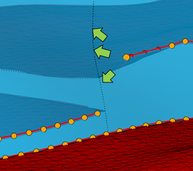
The option 'Keep movement in fault block' on the floating palette makes it impossible to move a node of a fault cutoff line into another fault compartment. The movement of the selected orange control node will be limited to the projected footwall intersection marked by the green arrows. click to enlarge
When you have completed editing the fault cutoff lines, click Apply or Next at the base of the Fault Cutoff Line Edits form, which will start the reconstruction of all the surfaces in your Structural Model, including the manual edits that you just did.